LP12: Plinth change and torque discussions
Moderator: Staff

Unfortunately I don't remember the exact day (no old age jokes :evil: ) but it will be sometime in the middle of June as it has been 33 years this month.SaltyDog wrote:Thomas, When is the big day? Just for the RECORD. :lol:
Oh, I don't know. If I was setting up LP12s over 5 years before they were made I wouldn't be on here talking to you lot!Charlie1 wrote:Well, at least it's not 45
 I'd be out using my time machine to make myself rich and travel the world (of course hitting each area at the peak of its glory - India 5,000 years ago anybody?). :mrgreen:
Too curious to wait long, and on top it’s raining:
Vertical spring dimensions are (all approx.) with outer platter and arm, and
corresponding forces
left 31 mm --> 1380 g
front 28 mm --> 1750 g
back 22.5 mm --> 2450 g
The latter is close to the limit of the range within which the spring can be used
reasonably, as 10 to 11 turns each 1.6 mm (diameter of spring wire) make
16 mm at least, so there are only about 6 mm left until complete blocking
occurs. This could be a reason to reduce the weight of the outer platter.
The Ekos was not as heavy as the SE (more than 100 g difference). The
sum of the above is about 5600 g.
Forces are estimated from
zero 43 mm
500 g 38 mm
1000 g 34 mm
1500 g 30 mm
2000 g 26 mm
Number 21 is now at the back position (as it was reasonably concentric
under large load), number 4 at the left position. The ones which had been
built in before were standard with respect to shape under load (i.e. like nr.1,3,
18 etc.) and my marks of the shortest radius with respect to zero load were
nothing worth under load. There is a systematic inclination to the right
when the downward spring end is oriented to the observer. This points at
the production process.
As expected by Thomas, turning of springs was still necessary.
Cryo-treatment: As far as I know one has to cool the material during the
production process. Is it true that cooling the springs shall have an effect
even long after this? (My fridge is minus 80 Celsius, it’s not exactly
mine,.but I can use it.)
-
Tony Tune-age

- Very active member

- Posts: 1661
- Joined: 2009-12-19 19:07
- Location: United States
ThomasOK wrote:
Basically, the current system is based on the dealer's skill and their dedication to getting your LP12 right. While the newer springs are better they are still not uniform, either statically or under tension, as Klaus has shown. Not only are they not mostly concentric but the tops and bottoms are not always level with each other. The good thing is that, at least as LP12 parts go, the springs are relatively cheap. So it is not too costly to throw them away. But also getting the bounce right is really about balancing the various non-linear forces to get them operating together in a basically linear fashion - not only balancing out the effects of eccentricity on the action of the spring but also of the different compression of each spring. So it really is about trial and error. I can tell you from experience that some LP12s seem to just fight you and require a few parts swaps and a fair bit of fiddling before they bounce well and others are fairly simple. I just finished doing an LP12 belonging to a friend who used to work for Linn and I fought for quite some time to get a really good bounce out of it. I straightened the bolts, swapped all three springs, one of them twice, and a couple upper grommets and did a fair bit of twiddling before I was happy with the suspension. When I mentioned this to the owner he allowed that he had never been able to get it to bounce well despite having swapped springs two different times! Other LP12s I really don't have to do that much to.
The good news is that it has been getting better. My experience is that the Keel is much more intolerant of the bolts not being perfectly straight but once they are it seems to also be easier to get a good bounce than with the steel subchassis. I believe this is because the upper grommet is a more precise fit in the Keel than the steel subchassis. So a Keel with really straight bolts and newer springs tends to be less work. But improved springs would certainly make things easier for us - as would perfectly straight bolts and perfectly cut locknuts but I'm not holding my breath. Making these items to the tolerances we would like is likely to be very expensive if Linn could even find a company to make them. And as Klaus points out the proper parameters haven't even been specified by the industry. Face it, bolts, springs, grommets and nuts were not designed with the usage we put them to in mind. Think how much more it costs to make a truly high precision subchassis compared to a standard one: Keel $3250, steel subchassis/armboard about $180.
In the end I'm just glad the LP12 works as well as it does as it still outperforms anything else I've heard. And as one who will soon be celebrating my 33 1/3rd anniversary setting up LP12s, I have to say: "You should have tried to set them up 30 years ago!"

All good points Thomas, and I understand why it can take a very long time to become a great Sondek Technician :!: Have a great LP12 (33 1/3) set-up anniversary 8)
Tony Tune-age
relevant or crazy?
Please comment whether you find the following idea naiv or relevant,
I’m not really sure.
I wanted to be able to observe the LP12 springs under the load they
have to carry when assembled. To do so, I mounted them upside down
on a plank with realistic distances between them. As they carry different
loads, they get compressed differently. I put pieces of wood with according thicknesses under the two at the tonearm side, so that the surface
defined by the upper spring ends should be approximately level.
Each spring is carrying a weight resembling roughly the load in the LP12,
but is not confined laterally, as I wanted to see how turning the
spring/grommet assembly would effect the geometry. The idea behind it:
It is best to find spring directional alignments which do not cause a need to
force the springs laterally away from their ‘natural’ location.
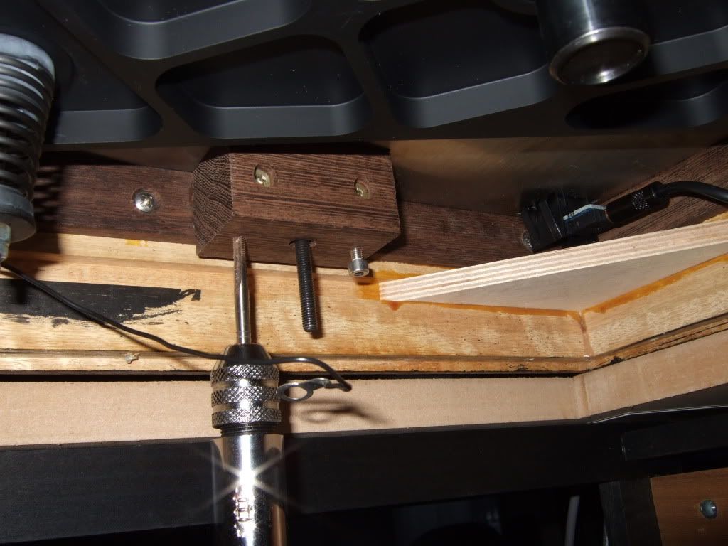
See what came out. I made a piece of transparent plastic with holes at
the centres of the spring bottom circles in order to check where the ends
should be. And quickly lost patience and initiative.
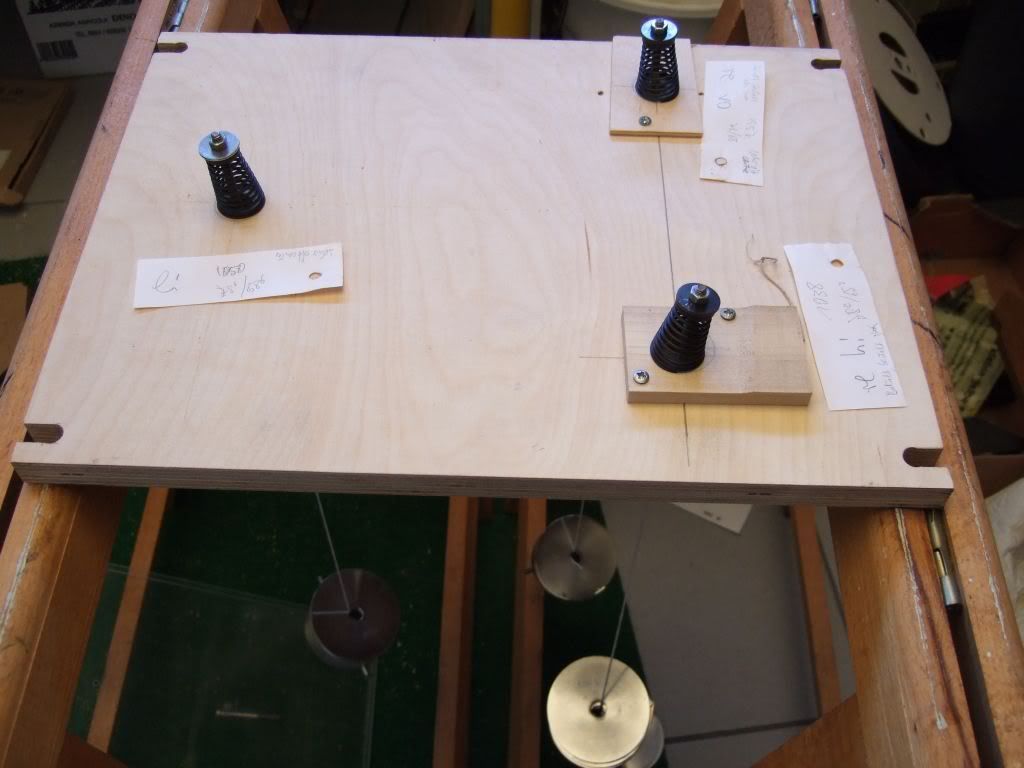
Overall setting
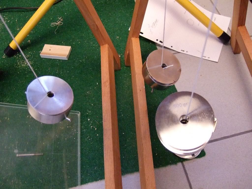
Weights hanging plumb
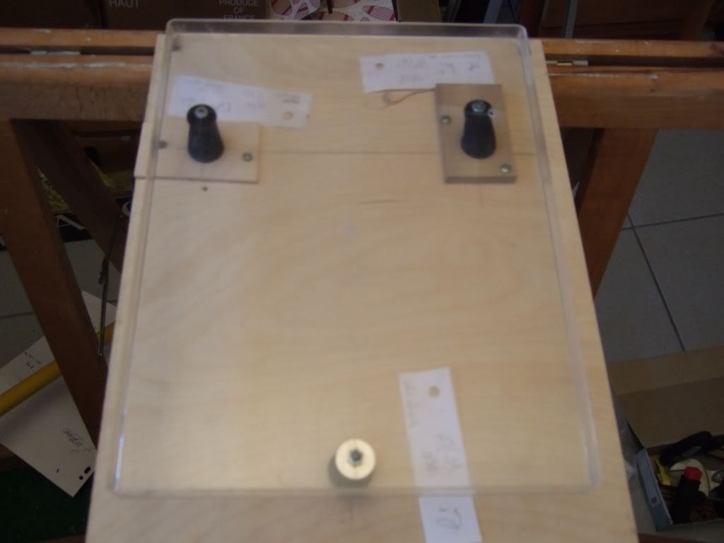
Fitting of the ‘bolt checker’
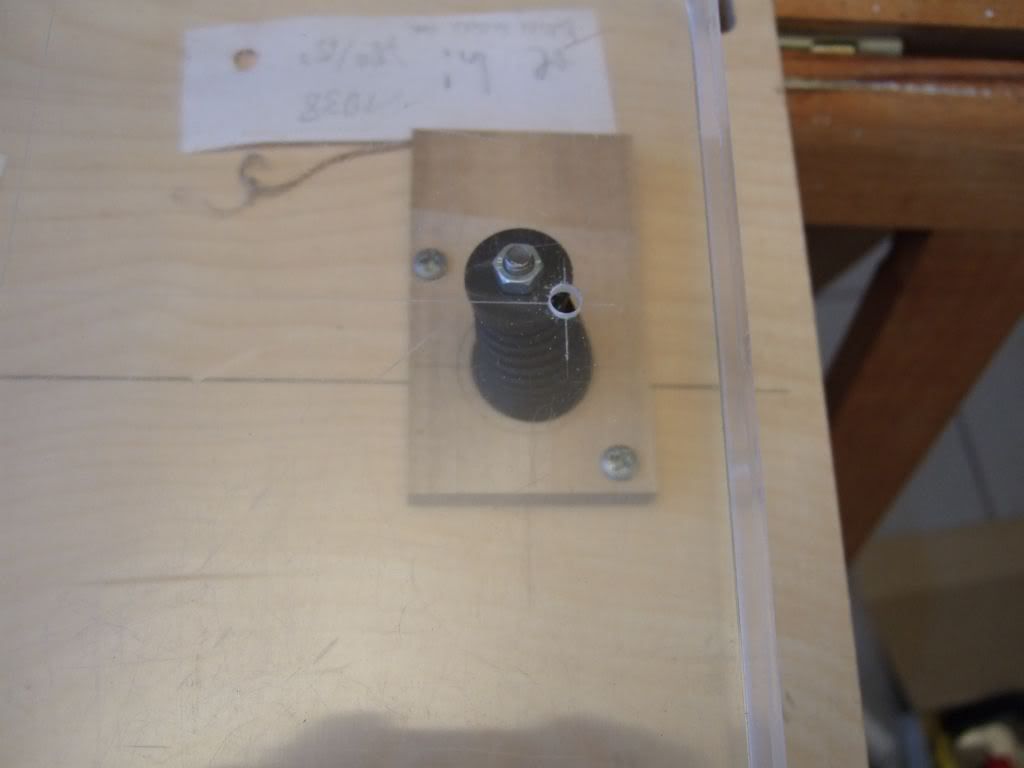
Situation at the third bolt (other two turned to fit)
I’m not really sure.
I wanted to be able to observe the LP12 springs under the load they
have to carry when assembled. To do so, I mounted them upside down
on a plank with realistic distances between them. As they carry different
loads, they get compressed differently. I put pieces of wood with according thicknesses under the two at the tonearm side, so that the surface
defined by the upper spring ends should be approximately level.
Each spring is carrying a weight resembling roughly the load in the LP12,
but is not confined laterally, as I wanted to see how turning the
spring/grommet assembly would effect the geometry. The idea behind it:
It is best to find spring directional alignments which do not cause a need to
force the springs laterally away from their ‘natural’ location.
See what came out. I made a piece of transparent plastic with holes at
the centres of the spring bottom circles in order to check where the ends
should be. And quickly lost patience and initiative.
Overall setting
Weights hanging plumb
Fitting of the ‘bolt checker’
Situation at the third bolt (other two turned to fit)
back to LINN plinth
As a number of forum members know, I returned back to the Linn plinth.
I think it is necessary to mention this here as well, because experiments
with the suspension continue and should be judged on the correct basis.
I must say, I was not in favor to change back, as the Movingui black plinth
was so nicely built and looked great. But I bought it for the sound, not for the look. And I
could simply not succeed and get a satisfying sound. The installation of an Ekos SE
brought about the final decision. Even when playing the new arm in the Movingui plinth,
a comparison with the Linn plinth/Ekos2 combi (Urika/Radikal cables separated)
gave the immediate impression: this sounds fundamentally right. (I'm
able to compare as I record all the changes using a couple of LPs.)
I then thought, it is not too much work to migrate the SE assembly back into the
Linn plinth (meanwhile I'm reasonably fast with that), and yes, it just sounded right
again.
My Movingui plinth gave an impression of seemingly more dynamics, seemingly more
definition, seemingly better discretion between instruments - all that called seemingly
as it was on the expense of musicality, playing together, tonal balance, integrity. What
it seems to do is emphasizing the upper register - this always has the above 'seemingly' effects.
(I encountered this with a couple of metal frame turntable supports, glass shelves &c. as well.)
Singers showed more sibilance and alto singers were going up on the scale. From
Kathleen Ferrier to Bob Dylan they were sounding wrong, while a drum solo would likely
be OK. While there was a feeling that one could perhaps favor the one ('fast') or
the other ('coherence') character when playing the Ekos2 (for me it's no question that I prefer the
latter), there was no question what to prefer when playing the SE. The SE displayed the
character of the plinth vividly as it is by itself so much more detailed, dynamic, and fast,
while keeping the music/musicians fabulously together.
At first I had no theory why this is so (and did not care as I was happy with my 'retro' installation).
Later on, I checked and knocked on this and that part of the Movingui plinth, and got the
suspicion (= opposite to knowledge!) that the ebony parts may have an adverse effect.
I was able to produce a very disharmonic sound when knocking on parts of the ebony
blocks which hold the top plate and cross brace (this seems to be an important location). It might
be that their extreme hardness is not beneficial. Similar considerations hold with respect to the
corner brace material. I don't think (again = opposite to knowledge) the Movingui itself is
ill suited. The large number of metal screws might also make an
effect (considering the presence of the back hinges should make a
difference). All this is, of course, pure speculation.
I fitted a new cross brace when turning back to the Linn plinth. It
turned out that the latest version has added elevated posts with M3 threads - these
interfere with the blocks. I had to machine two posts off to be able to mount the cross brace.
This cross brace had a non-painted area around the frontside bolt hole (though too small for
the 20 mm washers :-( ), obviously to improve earthing. To take advantage of that, I used
a non passivated standard sized washer and returned with my mass point to the bolt, using
the extra space method to avoid interference with the top plate bolt torque. Clear improvement.
In total, I must regard my conclusions from experiments with
the Movingui plinth as invalid with respect to a transfer to other plinths.
Of course, this is the conclusion of one person, two ears and hands
only. And this person has seen just this particular plinth. It is as always:
One has to look for a a/b comparison and choose what seems best
suited for oneself.....
Re: M4 done
Klaus,k_numigl wrote:As nobody seemed to have an opinion immediately I waited for this
weekend to check the M4 tapping. No objections arose either, so I
simply started, as I personally found it the right way to proceed.
I did not take the deck completely apart, but left as much as possible in
place, to be able to compare the single modification step. Screws are
now M4 3-mm-hex-head, 10 or 12 mm long, sorry, I forgot to record.
Washer and spring washer applied, too. They are now a delight to turn
and have been torqued to 0.4 Nm. This is pretty strong, and I don't
think I was at this point with the wood screws. As the latter have a much
steeper thread angle, too, contact force is most likely much larger now.
Isuspect the more important point is a more even distribution of
contacts.
Holes in the cross brace were enlarged to 5 mm to ensure that all
screws (and the bolts) are free of sideward stresses. Holes in the wood
and in the metal parts carefully deburred.
Musically it is a marked progress. Sound similar as before, but every
tiny bit and instrument much more at its well defined place. More
and impressing subleties to listen too, while maintaining pace and
drive. That's what we want from a LP12: detail _and_ bounce. Slowly
the performance gets to levels that surprise me.
I'm not completely sure whether to attribute this to the mod of the
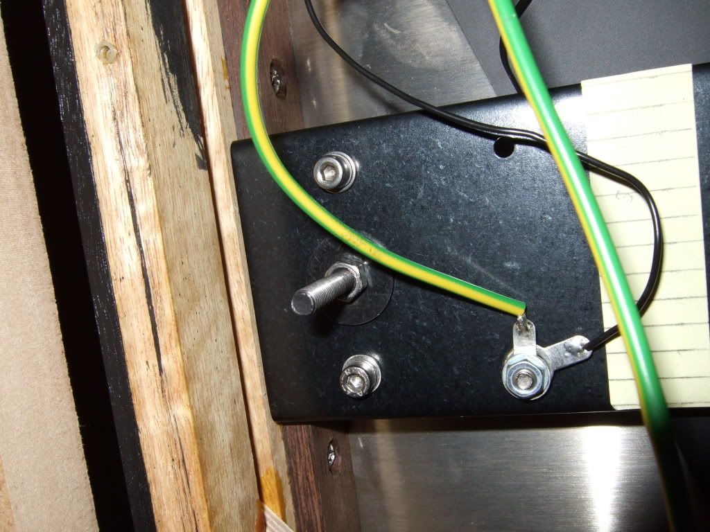
cross brace alone, as I also changed the position of the earth wire.
It annoyed me to have to dismount the earth wire connection point at
the bolt each time I want to change the torque there. The added mass
of tow nuts on this bolt could also be a compomise, I thought. Present
installation can be seen from the pic.
With this installation, the bolts could be shortened considerably,
reducing potential vibration at the free ends. Pros or cons seen for
this?
Regards, Klaus
did you try to replace the two wood screws holding the top plate near the bolts with two M4 3-mm-hex heads like you did for the cross brace ?
KR
matthias
-
Efraim roots
- Very active member

- Posts: 319
- Joined: 2009-10-23 01:37
- Location: Sweden
I'm borrowing this thread, hope you don't mind.
With Radikal you get more space inside the LP12. Have anyone tried to turn the p-clip 180 degres to give the T-kable less stress with good result, or is it better to have it the traditional way? Is the p-clip torque very important?
With Radikal you get more space inside the LP12. Have anyone tried to turn the p-clip 180 degres to give the T-kable less stress with good result, or is it better to have it the traditional way? Is the p-clip torque very important?
the players of instruments shall be there..
It is generally felt that the P-Clip is best oriented such that the cable runs between the post and the back of the plinth. However, the main benefit of this is that it puts it farther away from the power cable. With the Radikal this is no longer a concern as the power cable is no longer routed across the wiring strap but goes directly out the back near the motor. This being the case there might be an advantage in moving the P-Clip to the front of the post as this would allow a smoother curve out of the plinth. The main thing, however, is making sure the cable from the P-Clip to the arm base can move with the suspension as smoothly as possible and with a minimum of interference to the springs.Efraim roots wrote:I'm borrowing this thread, hope you don't mind.
With Radikal you get more space inside the LP12. Have anyone tried to turn the p-clip 180 degres to give the T-kable less stress with good result, or is it better to have it the traditional way? Is the p-clip torque very important?
There are people who feel that clamping cables tightly is not a good idea sonically so there could be some merit to repositioning it, but you have to be careful to make sure you don't change the tension of the cable between the P-Clip and the arm base. I haven't done a lot of experimenting with this but I do attach the cables to the cable routing of the Urika on the loose side. I have often wondered if not clamping the Radikal power cable too tight would have any benefit but have not experimented with it yet.
As to torque the P-Clip needs to be quite tight to make sure the cable is solidly connected at that point and the P-Clip can't move. I have not found this fixing to be sensitive to small torque changes like most other fittings.